Running the pipeline
Overview
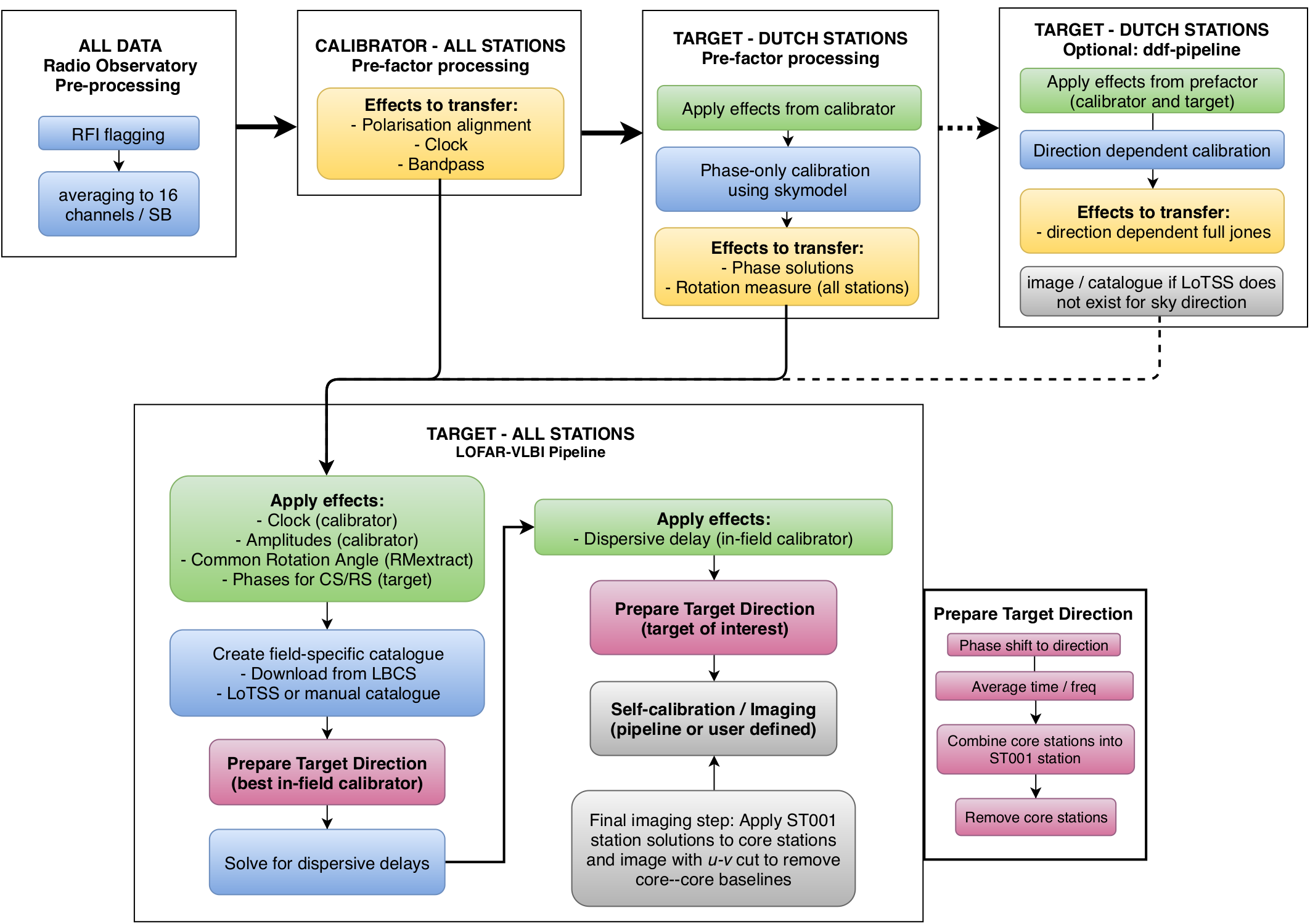
To produce high resolution images, there are four parsets you need to run. Two of these are from prefactor and two are from the LOFAR-VLBI pipeline. After you finish running the prefactor parsets you will need to assess the outputs before starting the LOFAR-VLBI parsets. These three sections are described in more detail below.
- Running Prefactor
- Pre-Facet-Calibrator
- Pre-Facet-Target
- Assessment of Prefactor output
- See guidance below
- Running the LOFAR-VLBI pipeline
- If necessary, configuring to use your own catalogue (see Using your own catalogue )
- Delay-Calibration
- Split-Directions
Prefactor in particular has many other steps you can run. These are not required for running the LOFAR-VLBI pipeline and therefore will not be covered here.
Running Prefactor
The LOFAR-VLBI pipeline makes use of prefactor solutions to apply to the data. Therefore you must pre-process your data through prefactor, both the calibrator and target pipelines. For instructions how to run prefactor on your data, please look at the prefactor documentation. For any issues you encounter with prefactor, please open an issue on the prefactor repository.
- The default is now for Pre-Facet-Calibrator.parset to process all stations, including the international stations. You can run this with the default settings. Please check the outputs to make sure they are sensible!
- The Pre-Facet-Target.parset should be run with all the standard defaults. This will copy over the solutions from Pre-Facet-Calibrator and add the self-cal phase solutions for the core and remote stations, which are necessary for the LOFAR-VLBI pipeline. Please check the outputs to make sure they are sensible! Also note any stations which were flagged as ‘bad’ as you will need to pre-flag these for the LOFAR-VLBI pipeline.
Note
Processing of interleaved datasets is not currently supported.
Assessment of Prefactor output
1. In the parent directory for your Pre-Facet-Target directory, there should be a Pre-Facet-Target.log file. This will tell you if any stations were deemed to be bad and automatically flagged.
The LOFAR-VLBI pipeline doesn’t have this information, so you have to manually set information in Delay-Calibration.parset manually to flag and filter any bad stations. The lines to change are ! flag_baselines = and ! filter_baselines =. Here is an example of the expecte syntax for flagging CS013HBA and removing it from the data:
## Stations to flag and filter
! flag_baselines        = [ CS013HBA*&&* ]
! filter_baselines      = !CS013HBA*&&*
Please note that the syntax is different for flagging, which sets the FLAG value to 1 to indicate bad data; and filtering, which is a selection function for NDPPP.
In this example we flag CS013HBA and all auto- and cross-correlations to/from that antenna, and then filter, i.e., select every antenna that is not CS013HBA to remove it completely from the data. The ! in front of the CS013HBA on the filter line is a negation – i.e., telling NDPPP to select everything except CS013HBA.
If you need to flag and filter multiple stations, here is an example of the syntax:
## Stations to flag and filter
! flag_baselines        = [ CS013HBA*&&*,RS508HBA*&&* ]
! filter_baselines      = !CS013HBA*&&*;!RS508HBA*&&*
Running the LOFAR-VLBI pipeline
The LOFAR-VLBI pipeline is broken into two steps: Delay-Calibration.parset and Split-Directions.parset. The first parset does all the heavy lifting; it applies the prefactor solutions, splits out best in-field calibrator candidate, performs the delay calibration on it, and applies these corrections back to the data. The second parset takes the resulting CORRECTED_DATA, splits out the directions in which you wish to image, and runs self-calibration on them.
Before running the pipeline, you should check:
- If there are any bad stations flagged by prefactor. These will need to be manually input into the parsets. Follow exactly the syntax for the example given in the parset.
- Check the rest of the “Please update these parameters” section. Comments in the parset(s) describe what they are.
- Optional: if you have run the ddf-pipeline, please update the DDF options as well. If you are only using the catalogue, update the lotss_skymodel parameter to point to your output file.
Trying a different Delay Calibrator
If you find that the delay calibrator selected by the pipeline is not adequate, or you wish to try a different LBCS source, you can do this with a little manual input.
First, you will have to modify the statefile (see prefactor documentation ) to remove the delay_solve step and everything afterwards, including the delay_solve directory in your runtime directory (although you may just wish to copy this to another name). You will then be able to resume the pipeline after making your catalogue changes.
Next, you need to modify (or insert) the delay_calibrators.csv file, which can be found in the results directory of your runtime directory. The name of the file must be delay_calibrators.csv and the following comma separated values, including the header, are required:
Source_id,RA,DEC
By default, the pipeline will have processed the first entry in the catalogue, which is sorted by increasing distance from the phase centre. If you wish to try the next source, simply delete the first entry and restart the pipeline after modifying the statefile / removing the delay_solve directory as described above.
Self-calibration or not?
The pipeline by default will run self-calibration and imaging as described below. Currently this assumes a point source starting model, which may not be appropriate for all sources. In the case of fainter sources with lower signal to noise, this may drive the self-calibration to an incorrect source structure. You may therefore wish to adjust the Split-Directions.parset to only run the setup steps. This can be done by changing line 75 of the parset to:
pipeline.steps = [ setup ]
The resulting measurement set will be appropriate to start imaging.